
Wi-Fi Antenna Installation Best Practices
Download the Full Whitepaper (PDF)Executive Summary
Key Takeaways:
- Proper antenna installation (height, orientation, clearance) has a major influence on Wi-Fi link performance in both indoor and outdoor applications.
- Line-of-Sight (LOS) and clearance of the Fresnel Zone are critical for point-to-point or point-to-multipoint links; obstructions degrade signal and throughput.
- Matching antenna polarization and selecting the correct type (omni, directional, panel) based on the application ensures optimal coverage and link stability.
- Cable and connector quality matter: feed-line loss, mismatches, and weatherproofing can undermine even the best antenna setup
- Maintenance, verification, and periodic re-alignment are needed to sustain performance over time (especially outdoors where conditions change).
Choosing the right antenna
The first step to building a wireless network is choosing the correct antenna for your application. Coverage and range will be the driving factors. Aesthetics may also be important. There are several styles of WiFi antennas with different radiation patterns, polarization schemes, and mounting options.
Omni directional Antennas
Omni directional antennas provide a 360° donut shaped radiation pattern to provide the widest possible signal coverage in indoor and outdoor wireless applications. An analogy for the radiation pattern would be how an unshaded incandescent light bulb illuminates a room. A high gain Omni’s vertical radiation pattern will exhibit a f lattened donut shape as shown below for the HG2415U-PRO antenna. Typical applications for Omni directional antennas include indoor office spaces, retail stores, warehouses, small office or home networks, outdoor cafés, campgrounds, RV parks and marinas. Examples of Omni directional antennas include the common “Rubber Duck” found on many WiFi access points and routers as well as the complicated antenna arrays used on cellular towers.
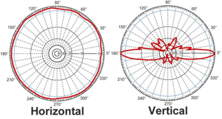
Typical Omni directional antenna radiation pattern (HG2415U-PRO)
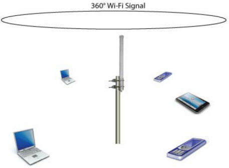
In the example above an Omni directional antenna is providing wireless connectivity for laptops, tablets, and smart phones in the coverage area.
Directional Antennas
A directional antenna, as the name implies, focuses the wireless signal in a specific direction resulting in a limited coverage area. An analogy for the radiation pattern would be how a vehicle head light illuminates the road. Examples of directional antennas include Yagi, Parabolic grid, patch, and panel antenna styles. High gain directional antennas can transmit and receive wireless signals for several miles given clear line of sight and sufficient transmit power. (More on line of site on page 6). Applications for directional antennas include point to point wireless links connecting buildings, a back-haul data link connecting cell towers together and point to multi-point wireless links where multiple remote clients with directional antennas communicate with a single central tower with an Omni directional antenna.
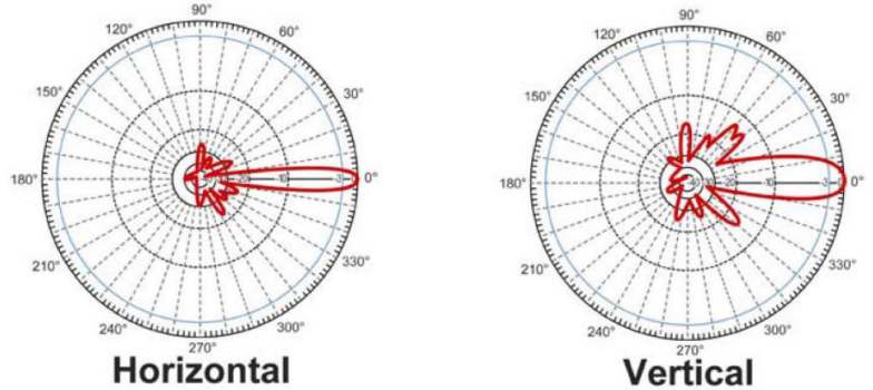
Typical Directional Antenna Radiation Pattern (HG2424EG-NF)
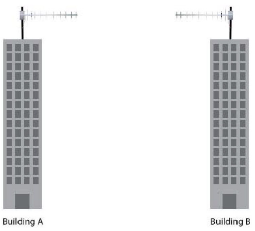
In the example above building A and building B are set up for a directional, point to point network using Yagi antennas.
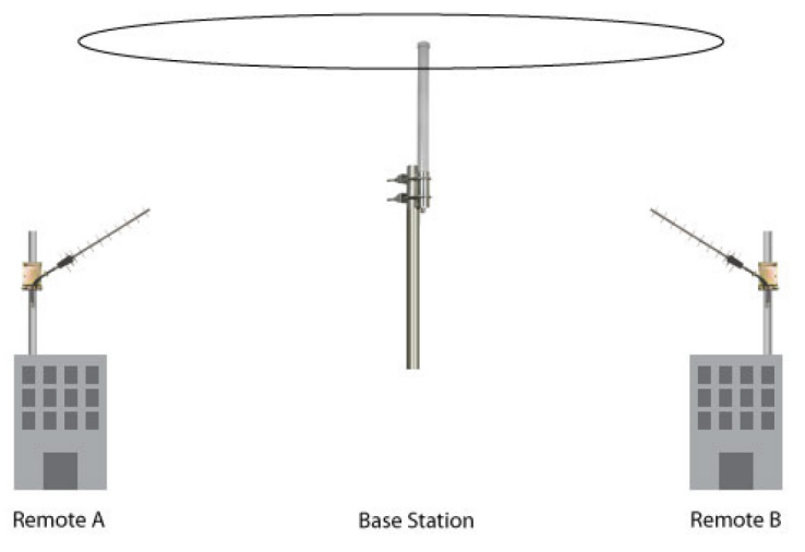
In this example both remote sites A and B have directional Wi-Fi connectivity to the base station fitted with an Omni directional antenna. This is an example of a point to multi-point set up.
Antenna Polarity
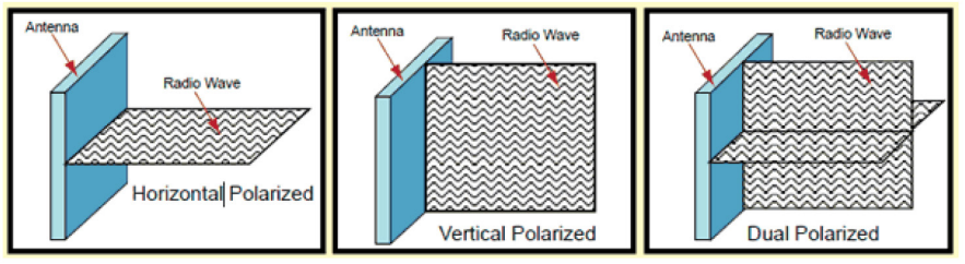
Polarization refers to the orientation of the electric field component of an electromagnetic wave with respect to the Earth’s surface. An electromagnetic wave is composed of electric and magnetic fields propagating perpendicular to each other. Radio and light are examples of electromagnetic waves. Electromagnetic waves can propagate with linear, circular or elliptical polarization. Linear polarization is the most popular method used in WiFi communications and can take two forms, vertical and horizontal. Polarity must be observed on both ends of a communication link. A properly designed antenna will offer 20 dB or more of isolation between the two polarities.
Dual Polarized Antennas
A dual polarized antenna uses extra internal elements to provide two polarities in a single package via separate input ports. For a linear design both vertical and horizontal polarities are available. For a circular design both right hand circular polarity (RHCP) and left hand circular polarity (LHCP) are available. The isolation between the two ports allows the antenna to transmit or receive two signals on the same frequency simultaneously.
Dual polarity antennas have multiple uses. In outdoor 802.11n multiple input-multiple output (MIMO) systems, the isolation allows the two MIMO streams to coexist without interference. For indoor 802.11g systems, polarization or spatial diversity can counteract the effects of multipath and fading. In DBS home satellite systems, polarization is used to allow twice the amount of transponders to be installed on a satellite.
Antenna Frequency
Antennas operate at different frequencies to suit different applications. The antennas frequency must match the frequency of the amplifier, access point, or router it will be attached to in order for the system to work. In the US the 900, 2400 and 5000 MHz frequency bands are set aside by the FCC for unlicensed Industrial, Scientific and Medical (ISM) applications. The lack of licensing requirements has greatly encouraged the growth of the wireless industry. These bands are used for consumer and commercial WiFi and WLAN applications as well as for commercial Radio Frequency Identification (RFID) and Supervisory Control and Data Acquisition (SCADA) applications. For the consumer the 2.4 GHz band is the primary band one uses for WiFi, Bluetooth, cordless phone, printer, keyboard, mouse and gaming controller applications. Cellular use licensed bands spread over the 700 – 2700 MHz range.
Antenna Gain
Gain is a relative measure of an antennas ability to direct or concentrate radio frequency energy in a particular direction or pattern. Gain is typically measured in dB over Isotropic point source, dBi. The analogy of an Isotropic point source would be a sun in the center of a universe. The choice of gain is dependent on system design, coverage, range, and transmit power. A higher gain number is not always the best choice. Gain and antenna type must be chosen to meet all objectives.
Antenna Installation Best Practices
Line of Sight
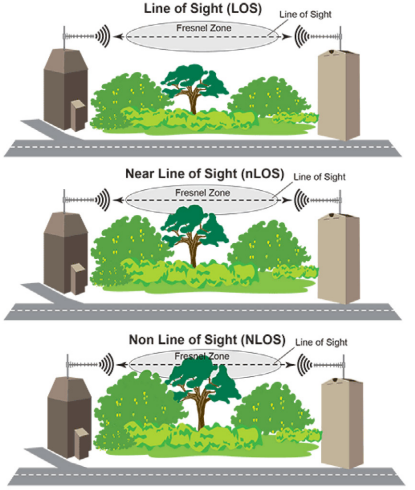
Whether you are installing a wireless network indoors or outdoors you must always consider line of site. The path between two antennas is referred to as the Line of Sight. There are three main categories of Line of Sight, the first being full Line of Sight (LOS) where no obstacles reside between the two antennas, the next is called Near Line of Sight (nLOS) which includes partial obstructions such as tree tops or buildings between the two antennas, and lastly Non Line of Sight (NLOS) where full obstructions exist between the two antennas. By determining the specific line of sight conditions in the WiFi network area you can then determine the correct type of wireless system to install.
Fresnel Zone - The area around the visual line-of-sight that radio waves spread out into after they leave the antenna. This area must be clear or else signal strength will weaken due to reflections (when wireless signals “bounce” off objects) that cause fading (loss of the wireless signal). Trees, buildings, towers etc. in the Fresnel Zone will produce reflections that can result in signal fading.
Path Loss
Path Loss is an area of concern for 2.4 GHz wireless systems. Although 2.4 GHz signals pass rather well through walls, they have a tough time passing through trees. The main difference is the water content in each. Walls are very dry: trees contain high levels of moisture. Radio waves in the 2.4 GHz band absorb into water quite well1.
Antenna Height (Outdoor Installations)
The correct installation height of an antenna depends on the factors outlined below.
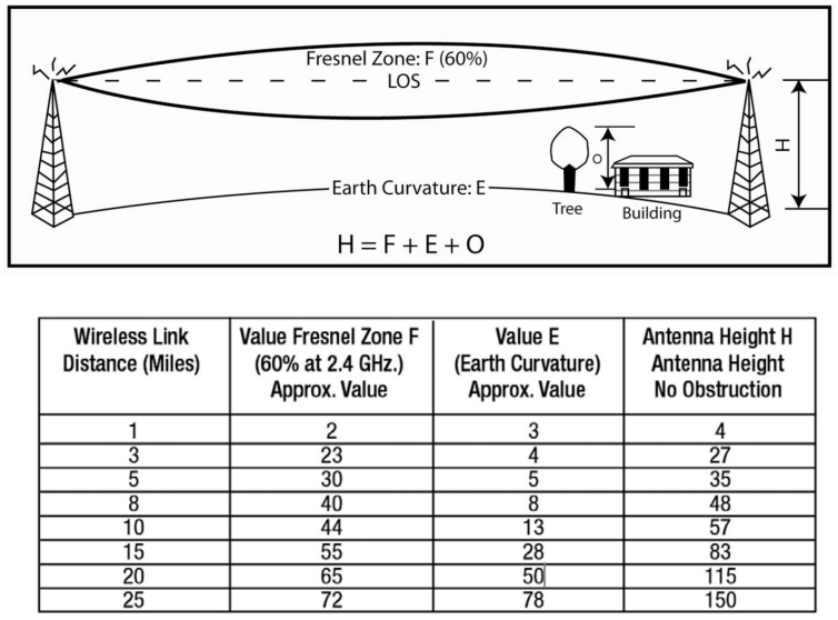
1) Distance between the sites: The longer the link, the higher the antenna needs to be due to the earth’s curvature.
2) The Fresnel Zone: See table 1 showing the 60% of Fresnel Zone values (accepted clearing on path). Add this to the earth curvature height.
3) Objects in the path: At a frequency of 2.4 GHz, you need a clear line of sight (LOS). Tree tops will deflect and absorb some of the signal. The theory is that the height of the tallest object in the path of the signal should be added to the Fresnel Zone and earth curvature clearance heights. You will need to check the height of the trees, hills, buildings or any object on the link path and add this to the measurement for the total of the tower height.
The above three conditions make up the Radio Line of Sight.
Outdoor Antenna Installation Best Practices
When installing an antenna outdoors is it important to use the minimum cable length required between the antenna and the access point or enclosure connection point. Also make sure the cable enters the enclosure or device from the bottom and leave enough cable to make a drip loop so rain and moisture will not enter the enclosure or equipment connections. Additionally we recommend that you wrap all outdoor cable connection points with moldable or self healing weatherproof tape. Also do not wrap the cable around a mast or pole. The cable should run straight down the mast from the antenna to the enclosure or WiFi amplifier.
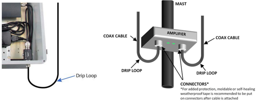
If you are using a wireless amplifier or radio it is best to position it as close to the antenna as possible (without putting too much stress on the connecting cables). Make sure the amplifier connectors are face down and leave enough room for drip loops.
Antenna Orientation (Indoor Installations)
When dealing with the installation and expansion of indoor wireless networks several factors must be considered. Most manufacturers of wireless access points and routers indicate a typical range that their equipment can provide. Usually these range estimates require line of sight which means you will need a clear unobstructed view of the antenna from the remote point in the link. In most cases there will be obstacles present in an indoor installation that could affect performance. Signals will be attenuated when they penetrate walls. Factors to consider include metal studs, concrete, fiberboard, aluminum siding, foil-backed insulation, pipes and electrical wiring, furniture and sources of interference. Sources of interference include other wireless equipment, cordless phones, microwave ovens and radio transmitters. In wireless transmissions, reflections (when wireless signals “bounce” off objects) and multipath (when wireless signals travel multiple paths to arrive at the receiver at different times) are as important as signal strength in determining the success of an installation. A signal will exhibit peaks and nulls in its amplitude and alteration of its polarization when propagating through walls, ceilings and reflecting off objects. In the case of indoor 802.11n/MIMO systems, multipath is actually required for the system to operate at the highest data rates. This is the rare case where a negative has become a positive.
Gain, Distance, and Loss Considerations
When planning your wireless network you first need to define the distance between wireless links or between the access points or radios. A link budget will need to be done. First you need to know the characteristics of the radio equipment being used. For every radio operating at a given data rate, there will be a specification listing transmit power and receive sensitivity. You also need to meet the minimum receive Carrier to Noise
(C/N) and Carrier to Interference (C/I) ratios. As the distance between your wireless points increases you must either increase antenna gain or transmit power. In general increasing antenna gain is the lowest cost way to increase range. There are numerous on-line tools you can use to calculate your range.
Cable Considerations
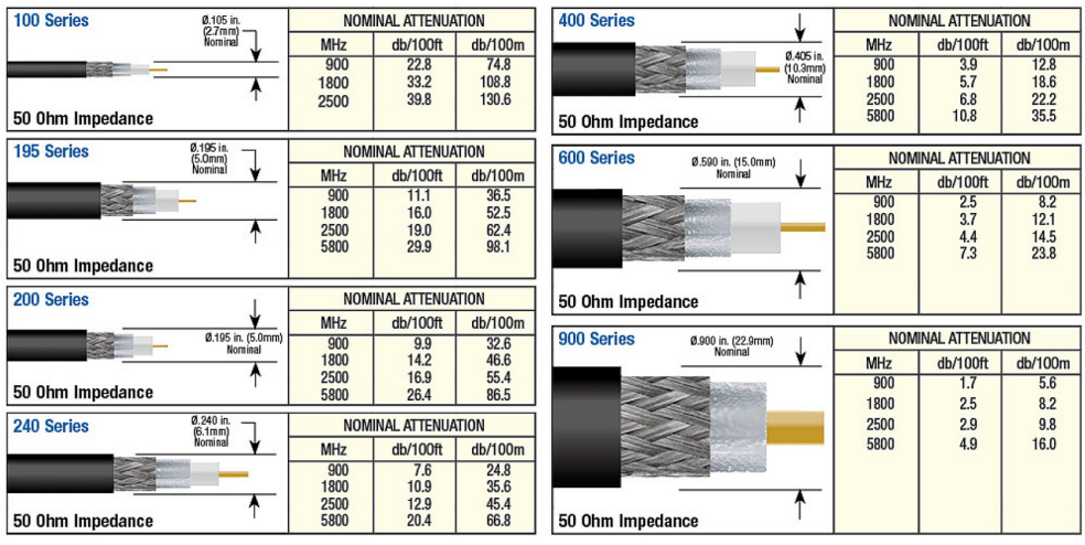
When designing a wireless network you should use 50 Ohm low loss coaxial cable for optimal results. This type of cable usually begins with a 100 series style up to a 900 series style. The lower the number of the series, the smaller the diameter of the cable. Lower number series cables such as 100, 195, etc. are used for very short pigtail connections to access points, surge protectors (in close proximity), and amplifiers. Larger series cable such as the 400 series are typically used for medium antenna cable runs and the 900 series is used for long distance applications such as base station tower installations that can be 100 feet or more off the ground. As a general rule, 195 series is good for distances under 20 feet, use 400 series cable for 20-50 feet, use 600 series cable for >50 feet. The chart on the next page defines the approximate loss values for the main types of low loss cables.
Recommendations
- Before installation, conduct a site survey to identify obstructions, RF noise sources, and optimal antenna mounting spots.
- Choose the right antenna type: e.g., an omni-antenna for coverage, directional for longer range links, panel for focused cellular/Wi-Fi zones.
- Ensure the antenna is mounted at proper height, away from reflective or obstructive materials, with minimal cable length and high-quality feedline.
- Budget for the premium: Accept that ruggedized cabling costs more but assess cost of downtime/failure in mission-critical systems.
- Use weather-proof connectors and includes grounding/surge protection for outdoor antennas to protect against environmental stress.
- After installation, perform post-installation verification: check RSSI/SNR, throughput and coverage maps; schedule periodic inspections for realignment and maintenance.
Key Installation Factors That Affect Wi-Fi Antenna Performance
Effective Wi-Fi coverage depends on following proven antenna installation best practices. This white paper focuses on the installation factors that most directly influence signal strength, interference and coverage, including antenna height and placement, Line-of-Sight (LOS) and Fresnel Zone clearance, polarization matching, and feedline and connector losses. It’s a practical reference for engineers and network professionals who want predictable Wi-Fi performance in both indoor and outdoor deployments.
Conclusion
Proper planning of your wireless network requires many factors to consider including the type of antenna(s) to use, the geography of the installation, interference factors, and other aspects of the network such as proper cabling to use, surge protection and best frequency for your application. By spending the time to consider all of these factors, you can ensure a successful wireless network installation.
Frequently Asked Questions
A: Omni directional antennas provide a 360° radiation pattern ideal for broad coverage areas like offices and retail stores. Directional antennas focus the signal in a specific direction, making them suited for point-to-point links between buildings or long-range connections.
A: Polarity must match on both ends of a communication link for optimal signal transmission. Mismatched polarity can result in significant signal loss, as a properly designed antenna offers 20 dB or more of isolation between the two polarities.
A: The Fresnel Zone is the area around the visual line-of-sight that radio waves spread into after leaving the antenna. Obstructions like trees or buildings within this zone cause signal reflections and fading, which weakens overall wireless performance.
A: 50 Ohm low loss coaxial cable is recommended for wireless networks. As a general rule, use 195 series for runs under 20 feet, 400 series for 20–50 feet, and 600 series or higher for runs exceeding 50 feet.
A: Higher antenna gain concentrates radio frequency energy in a specific direction, extending range. However, a higher gain number is not always the best choice — gain must be selected based on coverage goals, system design, and transmit power to meet all network objectives.