Engineering Resilient RF and Interconnect Architectures for U.S. Military UAVs
Download the Full White Paper (PDF)Executive Summary
Key Takeaways:
- Modern military UAVs operate in increasingly dense RF environments where multiple radios, antennas, sensors, and data links must coexist within compact airframes.
- RF integration failures are commonly caused by installation effects such as cable routing, connector stacking, antenna placement, shielding discontinuities, and electromagnetic coupling.
- Modular and attritable UAV architectures increase variability in RF paths, grounding schemes, and connector interfaces, creating greater system-level integration complexity.
- Mechanical vibration, thermal cycling, tight cable routing, and harsh operating conditions can degrade interconnect reliability and create intermittent failures that are difficult to diagnose.
- Early system-level planning for RF architecture, EMI mitigation, grounding, shielding continuity, and rugged interconnect design reduces qualification risk, rework, and integration delays.
In a classic technological tale, as one problem is solved, opening new avenues of innovation, new challenges arise. Modern military unmanned aerial vehicle (UAV) systems have solved many of the compute and software capability issues that affected development in the past. But there are new issues that engineers must account for — chief among them is the integrity of radio frequency (RF) and interconnect architectures.
Integration failures in the later stages of development can often be traced to RF performance degradation, interconnect instability, or electromagnetic interference (EMI) issues that only emerge under installed conditions. These failures arise during system-level testing, a time when reworking can be extremely costly.
By integrating more radios, sensors, and data links into smaller airframes, UAV platforms now feature increasingly dense RF environments with complex coupling paths. Contested electromagnetic environments in modern UAV platforms also require robust coexistence across communication, navigation, and payload systems. The shift toward modular and attritable UAV designs introduces variability in configuration that increases the likelihood of unforeseen RF interactions. In short, this type of design complexity introduces new RF issues for engineers.
Mechanical stress, thermal cycling, and vibration can degrade electrical performance over time, while poor grounding or shielding continuity can create unintended EMI pathways. These issues are rarely isolated; they are system-level problems that emerge from the interaction of components, installation practices, and environmental conditions. Interconnect systems (cables, connectors, and harnesses) are critical to improving outcomes around these problems.
By addressing RF architecture, interconnect reliability, and EMI considerations early in the design process, engineers can reduce rework, improve system robustness, and mitigate qualification risk to improve integration success.
Trends that Impact Military UAV Design
To accelerate prototyping and ensure mission-readiness, drone innovators must build at scale with reliable, speccompliant electronic components. Understanding the shifts in UAV design are essential to properly plan and execute next-generation drone development programs.
Increasing RF Density
Modern UAVs incorporate multiple RF subsystems. Command and control (C2), Global Navigation Satellite Systems (GNSS), telemetry, payload data links, and electronic warfare capabilities all must coexist within tightly constrained physical spaces. Even when antennas, cables, and RF components are distributed across compact structures, it’s often with limited separation. Packing this many systems and components into the small space of a UAV increases the chances of electromagnetic coupling, receiver desensitization, and unintended interference between systems.
Modular, Scalable, and Attritable Platforms
To enable more rapid reconfiguration and cost-effective deployment, UAV programs increasingly favor modular architectures. While this improves flexibility, it introduces variability in RF paths, connector interfaces, and grounding schemes. Each configuration change can alter RF performance, requiring robust design margins and standardized interconnect strategies.
EMI Ecosystem Evaluation
Where traditional EMI mitigation focused on individual component compliance, EMI challenges today are driven by system-level interactions caused by cable routing, shielding discontinuities, and antenna placement relative to structure and electronics. This means engineers must evaluate the full electromagnetic ecosystem rather than isolated components.
SWaP-C Optimization
Size, Weight, Power, and Cost (SWaP-C) constraints push designers toward lighter cables, smaller connectors, and tighter packaging. These optimizations offer advantages but can reduce mechanical robustness and shielding effectiveness, increasing susceptibility to failure in operational environments if not carefully engineered.
Problems to Address in Modern Drone Design
To create drones that keep up with design trends while meeting stringent military compliance requirements, engineers must adapt to meet a few major engineering challenges.
Plan for RF Performance Variables
When measured in a controlled lab setup, RF performance looks ideal because it removes the real-world variables that affect behavior in an actual UAV system. Once installed, performance shifts because the RF chain becomes part of a complex electromagnetic and mechanical environment. This happens, in part, because cable length, bend radius, and routing can increase insertion loss beyond datasheet values. Connector stacking is also a factor, as each additional interface introduces mismatch and loss, which can accumulate significantly in high-frequency systems. Proximity to conductive structures or other cables can also alter impedance and increase coupling.
In dense UAV architectures, antenna isolation becomes a critical design parameter because nearby structures and other antennas can distort radiation patterns, reduce gain, and introduce nulls depending on their placement relative to the airframe and ground planes.
Factor in Interconnect Reliability Concerns
UAV environments impose significant mechanical and thermal stress on interconnect systems. Continuous vibration from propulsion systems can loosen connectors, fatigue conductors, and degrade shielding integrity. Expansion and contraction across temperature extremes can cause micro-fractures or connector loosening. Tight routing and repeated flexing can lead to conductor breakage or impedance changes.
As these failures due to vibration and shock, thermal cycling, and mechanical strain happen intermittently, they can be extremely difficult to diagnose during testing. To deal with them, engineers must account for failure mechanisms such as connector disengagement, shield degradation, and cable jacket damage.
Prepare for EMI Issues
Cable harnesses are a primary pathway for EMI propagation. Gaps in shielding at connectors, splices, or terminations can allow RF leakage and coupling. Poor bonding between components and structure can create ground loops, impedance discontinuities, or floating reference planes. Parallel routing of high-power and sensitive signal lines can also increase the risk of coupling. In many cases, EMI issues are not caused by individual components but by how they are interconnected and routed within the system.
UAV Design Issues to Avoid
Don’t rely on isolated results: Validate performance in installed configurations early using representative routing and mounting conditions.
Avoid late antenna placement changes: Lock antenna locations early and validate with full-system RF simulations and testing.
Avoid excessive adapters and mixed connector families: Standardize connector interfaces and minimize transitions in RF paths.
Don’t rely only on component datasheets: Incorporate system-level testing to capture installation effects.
Don’t wait until after testing to fix EMI issues: Design EMI resilience into system architecture, including grounding, bonding, shielding continuity, and cable routing from the outset.
Best Practices for UAV RF and Interconnect Engineering
Follow these best practices to ensure your UAV systems live up to industry standards of reliability, compliance, and scalable production readiness.
- Define your frequency allocations, link budgets, isolation requirements, and coexistence strategies early on, during initial system design.
- Standardize your rugged interconnect design by using consistent connector families and vibration-resistant cable assemblies designed for harsh environments.
- Create more EMI-resilient cable routing and grounding by separating high-power and sensitive signals, maintaining shielding continuity, and implementing robust bonding practices.
- Validate harnesses under mechanical and thermal stress conditions representative of operational environments.
Solution Categories for UAV Design
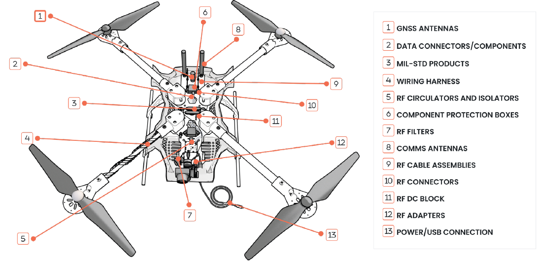
The following component categories are commonly used in military UAV RF and interconnect architectures:
- Low-loss, Vibration-rated RF Cable Assemblies
- Rugged RF Connectors and Adapters
- Antennas for C2, GNSS, Telemetry, Payload Links
- RF Components like filters, attenuators, and protection
- EMI/EMC and Grounding Accessories
Engineer’s Pre-Flight Checklist
Before your UAV takes flight, make sure you’ve gone through each of these steps: b
- Review RF coexistence
- Validate antenna placement
- Define cable routing rules
- Standardize connector interfaces
- Design for EMI mitigation
- Include installation loss
- Qualify harnesses
Plan Ahead to Avoid Common Pitfalls
Resilient RF and interconnect architectures aren’t just supporting elements. They’re foundational to reliable, mission-ready UAV systems. Issues like installation loss, connector reliability, and EMI coupling often emerge late in the development cycle, when they are most costly to resolve. Which means small decisions in RF architecture and interconnect design for UAVs can have big impacts on overall system performance and mission success.
By adopting a system-level engineering approach early on that integrates RF planning, interconnect design, and EMI mitigation, engineers can significantly reduce integration risk. Robust design practices, standardized interfaces, and real-world validation can ensure UAV platforms perform in operational environments, helping you to meet demanding requirements while you move faster from prototype to production, all without sacrificing performance.
Building More Resilient Military UAV Architectures
Strong RF and interconnect architecture design is essential for ensuring military UAV reliability, EMI resilience, and mission success in increasingly complex operational environments. Early system-level planning, standardized interconnect strategies, and robust EMI mitigation practices help reduce integration risk, improve long-term performance, and accelerate the path from prototype to deployment.
Frequently Asked Questions
A: Most RF failures during system integration testing trace back to installation effects that weren't captured during component-level validation. Cable routing, bend radius, connector stacking, proximity to airframe structures, and antenna placement relative to ground planes all shift RF performance from datasheet values. These factors are invisible in isolated component tests but become significant in the installed system.
A: Modular architectures improve mission flexibility but introduce variability in RF paths, connector interfaces, and grounding schemes. Each configuration change can alter RF performance in ways that weren't characterized during development. Programs using modular platforms need to design robust RF margins and standardized interconnect strategies that remain valid across all intended configurations — not just the baseline.
A: EMI analysis should begin during initial system design, before hardware layouts are finalized. The cost of fixing an EMI issue scales dramatically with program phase. An EMI problem caught during architecture review costs little to address; the same problem found during qualification testing may require harness redesign, shielding rework, and retest cycles that can delay a program by months.
A: Failures caused by vibration fatigue, thermal cycling, and mechanical strain tend to be intermittent. A connector that is fully engaged at rest may create a high-resistance or open-circuit condition only under vibration load, or only after repeated thermal excursions. These failure modes require stress conditions representative of operational environments to reliably detect — standard bench testing in ambient conditions will often miss them.
A: The most common mistake is treating EMI compliance as a component-level property rather than a system-level one. Even components that individually meet their EMC specifications can create significant interference when their harnesses are routed in parallel, when shielding is discontinuous at connectors or splices, or when bonding between components and airframe structure is inconsistent. EMI performance must be designed and validated at the system level.
A: Size, weight, power, and cost optimization often drives designers toward lighter cables, smaller connectors, and tighter packaging — all of which can reduce mechanical robustness and shielding effectiveness if not carefully managed. SWaP-C optimization and interconnect reliability are not inherently in conflict, but they require explicit design trade-off analysis. The goal is achieving the necessary performance margins with the minimum size and weight, not simply minimizing physical parameters without regard for operational durability.
