
The Benefits of Layer 3 Routing at the Network Edge
Download the Full Whitepaper (PDF)Executive Summary
Key Takeaways:
- IoT sensors convert real-world data into digital signals that can be stored, analysed, and transmitted.
- Layer 3 routing at the network edge eliminates the need for a separate external router, reducing hardware costs and wiring closet space.
- Layer 2 switching forwards frames using MAC addresses; Layer 3 routing uses IP addresses to direct traffic between subnets and VLANs.
- Edge Layer 3 switches support between 32 and 250 subnets per device — sufficient for end-user and access-layer deployments.
- Access Control Lists (ACLs), IP subnetting, and Layer 3 protocol filtering at the edge significantly strengthen network security.
- High-availability is achieved via redundant failover uplinks using protocols such as VRRP, without requiring core router traversal.
Introduction
With the advent of lower cost, widely available Layer 2/3 switching ASICs, the question now becomes when/where to use Layer 3 routing in the LAN. Traditionally, Layer 3 routers were always at the core of the network functioning as gateways to the Wide Area Network.
As technology, price points, and off the shelf availability have evolved, Layer 3 routing functionality is coming closer to the edge of the network right to the end user port. With this paradigm in Layer 2/Layer 3 convergence comes the question where and when is it necessary or beneficial to implement Layer 3 routing at the edge of the network?
Layer 2 Switching vs. Layer 3 Routing
First, let us explore the difference between Layer 2 switching and Layer 3 routing. Switching at Layer 2 (Data Link Layer) of the OSI model involves forwarding or filtering packets based on the MAC Destination Address (DA). A Layer 2 switch will dynamically learn the location of other IP Hosts on the network by logging each learned Source Address and the corresponding switch port it was learned on in the switches Address Table. When implementing Layer 2 switching, all packets are forwarded throughout the network unless specific filters are used to drop certain packets. Communication is open in this mode thus security and bandwidth conservation/containment are not optimized. When routing at Layer 3 of the OSI model (Network Layer), the forwarding and filtering of packets is based on specific protocol information and communication is contained within specific IP Subnets. Layer 3 routing allows intercommunication between different networks/users both geographically local and remote. Due to the more granular nature of Layer 3 routing lookups, as well as the implementation of Access Control Lists and Subnets in Layer 3 mode, Layer 3 routing provides greater security, control and bandwidth conservation than Layer 2 switching.
Some of the reasons for utilizing Layer 3 routing are LAN segmentation through subnetting, broadcast firewall security, intelligent wide area route determination/connectivity as well as overall relief from bandwidth congestion.
Today, LAN segmentation is done using Layer 2, 802.1Q VLAN. VLAN also provide network congestion relief and some level of security since there is no inter-VLAN communication that takes place. One drawback is that you must route at Layer 3 between Layer 2 VLAN in order for the different VLAN to communicate and share resources. Furthermore, in order to connect to the wide area network (the Internet) you must have knowledge/support of Layer 3 routers, routing tables, subnets and next hop gateways, these things cannot be achieved with a Layer 2 switch.
Since the introduction of web based applications and storage systems, the majority of end users must access the Layer 3 core. With 80% of all LAN traffic going through the routed core, whereas the old rule of thumb was 80% local to a Layer 2 VLAN or broadcast domain, implementing Layer 3 closer to the edge takes the burden off the core router as well as providing redundant, highly available, quick failover Layer 3 links via protocols such as VRRP.
Additionally, granular security rules can be administered via Layer 3 Access Control Lists on the edge router. Access Control Lists consist of one or more rules describing a particular type of IP or IPX traffic. ACLs can be simple, consisting of only one rule, or complicated with many rules. Each rule tells the Layer 3 switch/router to either permit or deny packets that match selection criteria specified in the rule. Each ACL is identified by a name. The name can be a meaningful string, such as denyftp or noweb or it can be a number such as 100 or 101. Examples of criteria which rules are set on for the IP protocol include:
- Source IP address
- Destination IP address
- Source port number
- Destination port number
- Type of Service (ToS)
Security features on Layer 2 edge switches are limited to filtering on specific MAC addresses, being filtered on either source or destination. Layer 3 Access lists are more versatile and granular in that more combinations of Layer 3/4 access criteria can be assigned thus creating more flexible, personalized security rules in the network from the edge to the core.
Furthermore, Layer 3 Multicast applications have become predominant in the Layer 3 routed world across WAN and into the LAN. By streaming voice and data, these multicast applications are widely used for distance learning as well as news and entertainment. The ability for multicast routers across the world to communicate requires knowledge/support of Layer 3 protocols such as DVMRP, IGMP and PIM-DM/SM for multicast applications. When Layer 3 multicast routing is supported in the edge switch/router, bandwidth, money and valuable closet space are conserved. Layer 2 IGMP Snooping does not provide multicast routing.
Configuration, management and administration of Layer 3 routing services at the edge, is typically less complex than in the core of the network. Today's edge switch/routers provide multiple management access and control gateways including web based Management, Telnet, CLI and SNMP based management access. Although some Layer 3 Routing education is required by the novice LAN administrator, basic concepts and guidelines are usually well documented in most edge product configuration guides.
Additionally, many Layer 3 protocols are dynamic once they are enabled. Initial configuration includes configuring IP Subnets for user groups and services, setting default gateways and enabling protocols such as RIP and DVMRP. The performance and cost advantage of implementing Layer 3 services at the edge of the network far outweighs the initial education process.
Recommendations
Layer 3 routing at the network edge represents a significant evolution in LAN architecture — one that improves security, availability, bandwidth efficiency, and cost-effectiveness simultaneously. By integrating routing directly into edge switches, organizations eliminate the need for standalone routers, reduce inter-switch link traversal, and enforce granular traffic policies closer to end users.
Whether you're designing a new campus network, upgrading an existing wiring-closet deployment, or evaluating multicast routing strategies for high-bandwidth applications, understanding when and where to apply Layer 3 at the edge is a foundational networking competency.
Defining Layer 3 Routing Protocols
To fully understand the operation and benefits of Layer 3 routing one must first have knowledge of the different protocols used. Below are some common Layer 3 routing protocols used in today's edge devices.
RIP (Routing Information Protocol) RIP is a distance vector routing protocol that is used for routing IP, IPX, and XNS protocols. The RIP packet includes information such IP address, subnet mask and next hop gateway info which allows communication with other RIP aware devices.
OSPF (Open Shortest Path First) OSPF, like RIP is a routing protocol. When implementing OSPF, each router obtains the entire topology database through flooding. Flooding insures a reliable transfer of the information. Each router then runs the OSPF algorithm on its database to build the IP routing table.
IGMP (Internet Group Management Protocol). IGMP is a protocol that is used by IP hosts (PCs for example) to report their multicast group memberships to an adjacent multicast routers.
DVMRP (Distance Vector Multicast Routing Protocol) - DVMRP routes multicast datagrams, between IP subnets. In addition, it specifies the tunneling of IP multicasts through non-multicast-routing-capable IP domains.
PIM (Protocol Independent Multicast) – PIM is a multicast routing protocol that runs over an existing unicast infrastructure. Unicast routing protocols include RIP and OSPF. PIM is called "protocol independent" because it can use the route information that any routing protocol enters into the multicast Routing Information Base (RIB).
There are two types of PIM, Dense Mode (DM) and Sparse mode (SM).
PIM-DM assumes that when a multicast source starts sending, all downstream systems will want to receive multicast datagrams. Initially, multicast datagrams are flooded to all areas of the network. If some areas of the network do not have group members, PIM-DM will prune off the forwarding branch of the multicast tree. PIM-SM is designed to efficiently establish multicast distribution trees across wide area networks (WANs) by selectively and intelligently sending multicast datagrams only to participating routers, which require them.
VRRP (Virtual Router Redundancy Protocol) VRRP is a protocol, which allows several routers on a multi-access link to utilize the same virtual IP/MAC address. One router will be elected as a master with the other routers acting as backups. All routers participating in VRRP will share each others IP/MAC information. Should one of the routers fail, immediate fail over to another active router will occur. The main benefit of using VRRP is that host systems (i.e. PC's) may be configured with a single default gateway and fail over time is at most only several seconds thus there is no effect on the IP Hosts or the applications that they are running. Additionally, VRRP supports load sharing of traffic when Default Gateways are configured appropriately. Utilizing VRRP guarantees network availability.
Layer 3 Routing Applications
Below are some applications where Layer 3 routing is necessary and/or beneficial at the LAN edge. The following applications are typical for most LAN.
Example 1: Assigning Static IP routes to VLAN/Subnets
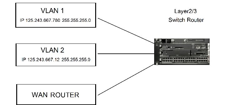
In the case of basic IP routing at the edge of the network, a VLAN equals an IP Subnet. With static IP routing, each VLAN, or Subnet, is statically assigned an IP address by the network administrator. By statically assigning IPs to VLAN/Subnets, greater control, accuracy and security are guaranteed. In a traditional Layer 2 network, 802.1Q VLAN may be used to segment users groups; this application is similar to IP Subnetting although when using Layer 2 VLAN no communication is allowed between VLAN. When Routing at Layer 3 individual users or subnets may be configured for intercommunication and resource sharing. This is beneficial when several user groups or individual users must access the same server/s but are not allowed to communicate with each other.
With Layer2/3 switch-routers, any VLAN configured on the switch that is not assigned an IP subnet, will act as a Layer 2 VLAN and will not be routed, even if the switch is in IP Routing mode.
Typically, Layer 2/3 edge switches will support between 2k to 16k IP addresses per switch. Furthermore Layer 3 Subnet/IP interface support is usually between 32 and 250 subnets per switch. Since Layer 2/3 edge devices are connected to finite users/services, the above support is acceptable. For Core Layer 3 routing solutions, larger tables are needed due the aggregation of many switches, routers, server farms and multiple geographically displaced devices/users. Again, routing is necessary to communicate between disparate Layer 2 802.1Q VLANs.
Example 2: Routing between Layer 2 VLAN
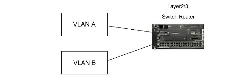
In order for communication and resource sharing between Layer 2, 802.1Q VLANs, Layer 3 routing is required. The advantage of today's Layer 2/3 switches is that no external Layer 3 router is required saving money and valuable wiring closet space. Additionally, bandwidth is conserved due to the fact that multiple inter switch links do not need to be traversed for core Layer 3 routing decisions, all of this activity occurs in the same ASIC/backplane of the edge switch/router. The protocol used in this scenario for basic Layer 3 routing between VLAN is RIP (Routing Information Protocol). RIP is a distance vector routing protocol that is used for routing of IP, IPX, and XNS protocols. The RIP packet includes information such IP address, subnet mask and next hop gateway info.
Example 3: Routing on high speed uplinks to the core
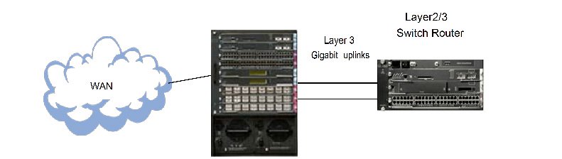
In this example, all Layer 2 users connected to the switch/router access high speed Layer 3 Gigabit ports connected to the backbone router which is in turn connected to the WAN. The benefit of Layer 3 on the Gigabit uplinks in the edge switch/router is that less network bandwidth is used traversing links between the core router end edge switch. All Layer 3 look-ups and routing decisions are determined within the ASIC contained in the edge switch/router closest to the end users. More importantly, redundant, highly available quick fail over links are established via VRRP. Because of this, total system availability is ensured when routing on the uplinks at the edge of the network. Traditional Layer 2 Spanning Tree reconvergence time can take up to 45 seconds. The typical Layer 3 VRRP reconvergence time is generally sub two seconds.
Example 4: IP Multicast routing with IGMP and DVMRP
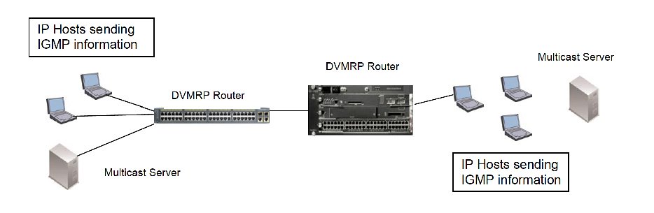
In the example above, individual IP Hosts, or laptops in this scenario, use IGMP to send data about which multicast groups they are members of or would like to join. The DVMRP routing function in the Layer 2/3 switch routers then route IGMP information (joins, leaves etc.) between different IP subnets in the LAN. By supporting both IGMP and DVMRP multicast routing, today's switch/routers save time and bandwidth by not having to traverse multiple links to a traditional core router, which up until recently, provided this intelligence.
In contrast, IGMP snooping at Layer 2 provides intelligent multicast scoping and awareness by determining exactly which users groups are located off each port on the switch. This provides bandwidth control by not flooding all requests and advertisements to ports/users that are not members of specific multicast groups requesting the multicast stream. The drawback is that routing between IGMP multicast groups is not supported with Layer 2 IGMP Snooping. The Layer 2 switch must send IGMP requests and reports across multiple inter-switch links and into the Layer 3 Multicast router somewhere in the core of the network in order to communicate with other Layer 3 Multicast routers and servers which contain the requested multicasts. By employing Layer 3 multicast routing at the edge, within the switch/router, bandwidth conservation is realized since all multicast routing decisions are made locally within the edge switch/router. Additionally, a separate multicast router does not have to be purchased saving both cost and closet space.
Example 5: This example illustrates the use of PIM-DM multicast routing in the LAN
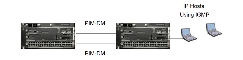
PIM-DM is similar to DVMRP in that it is a Layer 3 Multicast routing protocol. PIM-DM is flooded to all PIM-DM aware routers in the LAN to share multicast sender and receiver information. This flooding approach guarantees that all senders and receivers are accounted for and added/deleted from multicast routing tables accordingly. PIM-DM is less efficient in WAN applications where multicast senders and receivers may be widely dispersed. Again, multicast routing is not supported by a Layer 2 only switch.
Example 6: This example illustrates the use of PIM-SM multicast routing protocol
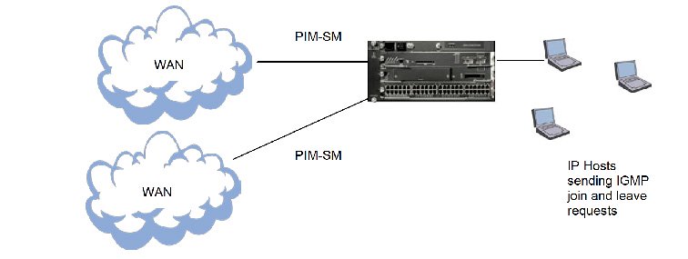
Here, the Switch/Router is directly connected to the WAN. PIM-SM was designed to operate very efficiently across wide area networks, where multicast groups are sparsely distributed. PIM-SM uses join requests that transmit from router to router from requesting IP Hosts to directly connected routers that share the same multicast groups being requested. PIM-DM on the other hand uses the flooding mechanism to build its tables. Such mass flooding to few, geographically dispersed routers in the WAN would be very inefficient, this is why Sparse Mode was created.
Again, the benefits for using PIM-DM or SM, depending on the application, LAN or WAN, are the same as those found when implementing DVMRP Multicast routing. All of these protocols allow for IGMP communication between subnets, this is something that a Layer 2 switch cannot do.
Example 7: In this example, OSPF is used to route IP traffic through the LAN and into the Core router
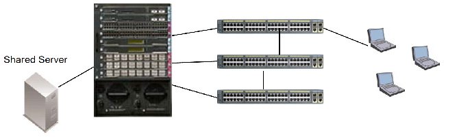
OSPF uses an algorithm that selects the shortest open path between routers. The laptop users above are in different IP subnets, each with different IP addresses. In order to communicate with shared resources (i.e. printers/servers) as well as the WAN via the core router, Layer 3 routes must be established. OSPF will determine the best, fastest route to those resources. Each OSPF router maintains routing tables of all other OSPF routers for best route determination.
Example 8: Using VRRP in the LAN
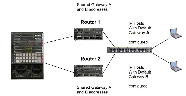
The above example shows how VRRP enabled on the two Chassis based Switch routers as well as the core router. In the case where a link to the chassis based switch router were to fail, all traffic destined to the already configured default gateway on the LAN IP Hosts will be diverted to the other, operational chassis based switch/router. In order to gain load balancing as well as redundancy, one half of the users (PCs) on the standalone switch are given a specific IP gateway and the other half are given a different IP gateway. This ensures that a single interface will not be "over run" and congested due to high volumes of traffic, Also, this ensures that if one IP gateway were to fail, the other will take over ensuring total network availability.
Furthermore, VRRP supports a sub-two second fail over time, which insures critical applications will not time out and there is no impact to the end user/host systems.
In contrast, Spanning Tree Protocol used in Layer 2 networks will typically take up to 45 seconds to respan after a link is disabled. This could cause critical network applications, to time out. Additionally, Layer 2 Switches, when connected to each other, send BPDU (Bridge Protocol Data Unit) packets as broadcasts throughout the entire network. All switches/bridges in the LAN send and receive these BPDU's. This adds to overall network congestion in the LAN. In contrast, when utilizing Layer 3 VRRP, BPDU broadcasts are not propagated throughout the LAN.
Next Steps
Layer 3 routing at the network edge represents a significant evolution in LAN architecture — one that improves security, availability, bandwidth efficiency, and cost-effectiveness simultaneously. By integrating routing directly into edge switches, organizations eliminate the need for standalone routers, reduce inter-switch link traversal, and enforce granular traffic policies closer to end users. Whether you're designing a new campus network, upgrading an existing wiring-closet deployment, or evaluating multicast routing strategies for high-bandwidth applications, understanding when and where to apply Layer 3 at the edge is a foundational networking competency.
Conclusion
By implementing Layer 3 at the edge of the LAN, many benefits are realized. These benefits include greater network security via access control lists, Layer 3 protocol filtering and IP Subnetting, availability through high speed, redundant fail over uplinks via protocols such as VRRP, intercommunication between Layer 2 VLAN, WAN connectivity, and increased bandwidth conservation by limiting the need for users to traverse multiple inter-switch links into a core router for Layer 3 decision making.
Additionally, money is saved since it is not necessary to purchase an external Layer 3 router in addition to a Layer 2 switch. Furthermore, wiring closet space is conserved since all Layer 2/3 functions are performed in a single unit.
With lowering price points and off the shelf support for Layer 3 routing in today's ASICs it is a must to factor in Layer 3 support through the entire LAN edge to core, for future investment protection. By supporting Layer 2/3 functionality in today's network edge devices, future expandability, functionality and efficiencies are guaranteed. As more applications and resources depend on Layer 3 support, installation of Layer 2/3 switch routers today guarantees investment protection for tomorrow.
Moreover, by implementing Layer 3 at the edge, the overall Service Enabled Edge is enhanced. By adding Layer 3 protocol filters, Access Control Lists and IP Subnetting, more granular user requirements and levels of access are addressed. In the traditional Layer 2 environment, individual user requirements, access and control are limited.
By implementing Layer 3 routing at the edge, greater security, availability and network utilization are realized.
Frequently Asked Questions
A: Layer 3 routing at the network edge refers to implementing IP routing capabilities directly within access-layer or distribution-layer switches — the devices closest to end users — rather than relying solely on a centralized core router. This approach allows inter-VLAN communication, subnet routing, and WAN connectivity to be handled locally, reducing latency and hardware costs.
A: Layer 2 switching forwards traffic based on MAC addresses within a single broadcast domain. Layer 3 routing uses IP addresses to move traffic between different subnets and VLANs. Without Layer 3 routing, devices on separate VLANs cannot communicate directly — all inter-VLAN traffic must traverse an external router.
A: Layer 3 edge routing is ideal when you need inter-VLAN communication in environments with fewer than 250 subnets per switch, want to reduce bandwidth consumption by keeping local traffic local, and want to avoid the cost of a separate Layer 3 router. It is particularly beneficial in wiring-closet and access-layer deployments.
A: Common protocols include RIP (simple distance-vector routing for small networks), OSPF (link-state routing for larger, scalable LANs), DVMRP and PIM-DM (dense-mode multicast for LANs), and PIM-SM (sparse-mode multicast for WAN multicast groups). The right choice depends on network size, topology, and multicast requirements.
A: Yes. Edge Layer 3 switches can enforce Access Control Lists (ACLs), apply Layer 3 protocol filtering, and leverage IP subnetting to isolate traffic by segment, department, or device type. This reduces reliance on a central perimeter device for all security enforcement and limits the blast radius of internal threats.
A: Modern Layer 2/3 switches with built-in ASICs that support IP routing are sufficient. Off-the-shelf hardware now commonly includes Layer 3 capabilities at competitive price points, making it unnecessary to purchase a separate external router for edge routing functions.