
Industrial Ethernet
Download the Full Whitepaper (PDF)Executive Summary
Key Takeaways:
- Industrial Ethernet ensures high-speed, reliable communication in harsh environments.
- Use shielded, industrial-rated cables and connectors for EMI and mechanical protection.
- Choose the right topology and redundancy strategy for uptime and safety.
- Separate signal and power wiring to prevent interference.
- Regular maintenance and testing are essential for long-term performance.
Introduction: Why Industrial Ethernet Matters
The landscape before Industrial Ethernet saw a division between the office network and the industrial (factory, process) network. The reason for this is that networks used in manufacturing and process applications must be deterministic. Deterministic networks guarantee a data packet or message will be received at a certain time always with no exception. As Ethernet is a non-deterministic technology it had no place in an industrial network environment. For example, in an Ethernet office network if an e-mail or file on a server is not able to be accessed or does not arrive at the destination of the end user, business will go on and eventually the e-mail or file will be accessed when the network becomes available again. On the other hand, if a control signal sent to flow value in an oil refinery is not received within a certain time frame a tank may overflow causing damage, injuries and loss of money.
The original Ethernet architecture employed shared network access using an access method called Carrier Sense Multiple Access with Collision Detection (CSMA/CD). The way this worked is that before an end node sent a packet it would “listen” to see if any other node was transmitting on the network before it tried to send its packet. If the network was busy, then the packet would not be sent for some time. In the event two nodes sent packets simultaneously there would be a collision and the nodes would then need to resend their packets after waiting for a period. In some cases, a broadcast storm occurred when multiple nodes were trying to access the network at once and would cause the whole network to freeze up.
This shared architecture was also very inefficient in that each user connected to the Ethernet network would “see” all of the requests being sent from a single end node “looking” for the destination node. This used up unnecessary bandwidth and got even worse as more nodes were added to the network. As outlined above the original implementation of Ethernet was highly non-deterministic and could never be used for industrial networks where timing and predictable latency are critical.
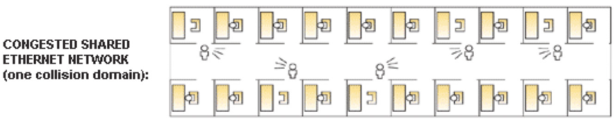
The diagram above depicts a classic shared Ethernet network where multiple users are all trying to communicate on the network at the same time causing collisions and network congestion.
Ethernet Switching
In 1990 the Silicon Valley based company Kalpana developed the Ethernet Switch. The new switching technology eliminated the previous shared architecture by using an address table based on an end nodes Media Access Control (MAC) address. The MAC address is a unique code that is “burned into” every network enabled device. The switch would build a table that recorded which port on the switch each MAC (end device) was located. After the switch “learned” all of the MAC address port locations it built a source and destination address table that was essentially a map of where each user was located. This produced a point to point network where for example when User A wanted to talk to user D, the switch received the request to transmit packet from user A, looked at the address table to see user D was on port 3 and forwarded the message to User D on port 3. This new technology provided great efficiencies over its shared network predecessor by alleviating network congestion and dropped packets due to collisions.
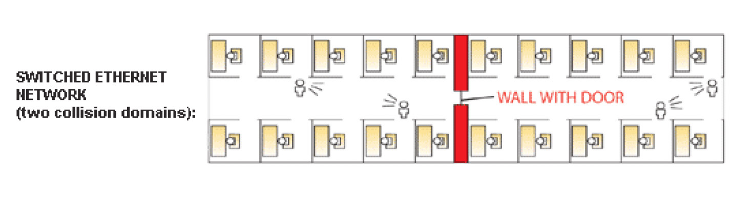
The diagram above represents s switched Ethernet network with two separate collision domains. This segmentation is done using the switch’s address table where peer to peer connections eliminate collisions.
Along with the advent of switched Ethernet came the ability for full duplex communication. Full duplex allows a node to transmit and receive at the same time to another connected node providing a collision-free environment and doubling the bandwidth capacity compared to the older half duplex Ethernet implementation where a node could only send or receive data at one time. By utilizing switched, full duplex Ethernet more deterministic behavior was realized but this new architecture was still not resilient or predictable enough for use in deterministic industrial networks.
Further Developments in Ethernet
As switched Ethernet evolved more need was seen for further segmenting of the network to improve performance. The introduction of IEEE 802.1Q Virtual LANs or VLANs made it possible to define logical groups of users who would only receive packets from other users in that VLAN group which meant greater utilization of network bandwidth and added efficiency. VLANs also added a new layer of security since different VLANs could not communicate between each other without the use of a Layer 3 router which could be programmed with specific access rules defined by a network administrator
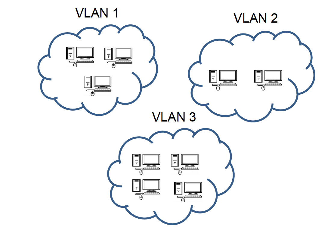
The diagram above represents VLAN segments where only the users or nodes in VLAN 1 can communicate with each other. This segmentation provides security as well as traffic optimization.
Along with 802.1Q VLANs the IEEE released the 802.1p traffic prioritization scheme which defined up to eight different priority levels (0-7) that could be assigned to allow more mission critical traffic to be processed through the network before lower priority traffic. 802.1p further closes the gap between deterministic and non-deterministic networks by allowing critical traffic/applications network access over lower priority traffic.
Another development in Ethernet functionality was the introduction of Internet Group Management Protocol (IGMP) Snooping. IGMP is a protocol used by hosts or nodes and local multicast routers on IP networks to set up multicast group memberships.
Multicast is a one-to-many architecture where for instance a multicast server sends a single video stream to several different nodes via a multicast router. The benefit of using IGMP for multicast applications is that only users who “sign up” for the multicast will receive it thus freeing up network bandwidth for other services and types of traffic. The IGMP Snooping feature found on many Layer 2 Industrial Ethernet Switches “listens” to the communications between multicast routers and hosts to see which host needs which multicast stream. By knowing which host needs which multicast traffic the switch will filter unwanted multicast traffic coming from the multicast router freeing up bandwidth and eliminating network congestion.
Some other features that were added to Ethernet switches to prevent network congestion and improve network performance were port level broadcast, multicast and unicast storm control. For example, if a network interface card (NIC) on a PC were faulty and started sending broadcasts into the network, the switch would detect the errant behavior and turn off the switch port the PC was connected to thus protecting the rest of the network from being f looded with packets and degrading network performance.
Rate Limiting is another feature which helps maintain network performance, stability and efficiency. Rate Limiting allows a network administrator to set certain data rates per port on the switch. This will ensure critical services or devices are allowed more bandwidth on the network than other non-critical services.
802.3x Flow Control is another method that was developed to ensure network stability in the event a sending node is transmitting traffic faster than the receiving switch or node can accept it. In this case the overwhelmed switch sends a PAUSE frame to the sending node which stops it from sending traffic for a specified amount of time until the receiving node has enough resources to accept the transmission from the transmitting node.
Another factor to consider in the evolution of Ethernet is the increase in speed. In the beginning Ethernet networks operated a 10 Mbps, and then 100 Mbps. Today many switches offer 1,000 Mbps or 1 Gigabit per second speeds. Additionally, 10 Gbps interfaces for trunk connections or inter switch link connections are also common place today. The advantage of these higher data rates is that if an error occurred and a packet needed to be retransmitted, or the network was congested the speed of the re-transmission is so fast that almost no latency is realized. This great speed increase helps Ethernet to be a more deterministic architecture for use in industrial networks.
Redundancy and Availability
A critical design element for industrial networks is redundancy at the physical level. Having a secondary or tertiary link for traffic to fail over to in the event of a broken cable or equipment failure is critical to the network. With Layer 2 unmanaged Ethernet switches that are often referred to as plug and play, if the cabling is not connected correctly then a data loop may occur which can take down the network. Managed Layer 2 switches utilize IEEE 802.1D Spanning Tree Protocol (STP) which was developed to allow a redundant connection to a switch to ensure network uptime and availability.
The way Spanning Tree works is that one switch in the network is assigned a port to be in standby mode where it will not send or receive data until a break or disruption occurs to another link in the network. When a disruption occurs the standby port on the switch will become active to allow traffic to flow on the network. The disadvantage of traditional STP is that it can take up to 60 seconds to respond to a topology change caused by a cable break or disruption. This is much too long for a critical process or manufacturing application where micro seconds count.
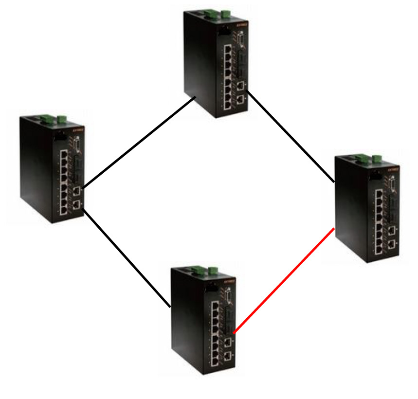
In the diagram above the red link is set to standby mode and will not transit packets unless a break or failure occurs in one of the other links. This represents the basic spanning tree operation where link redundancy is achieved without creating data loops.
In 2001the IEEE introduced 802.1w Rapid Spanning Tree Protocol (RSTP). RSTP provides significantly faster topology change detection and recovery within 6 seconds (default). Although RSTPs the recovery time is much better than STP it is still too long for some critical industrial networking applications.
Many Industrial Ethernet switch manufacturers offer their own proprietary fast ring technologies where a break in the ring will be resolved in microseconds. Some of these include EtherWAN Systems α-Ring technology which provides a rapid fail-over recovery time of less than 15ms, GarrettCom’s S-Ring and Hirschmann’s HiPER Ring protocol.
Additionally, hardware redundancy is available from most industrial switch manufacturers today by providing dual power inputs for a switch. In the event of a power supply failure or other power disruptions, the switch will automatically fail over to the secondary power supply keeping the network up. Furthermore, the design of industrial Ethernet switches excludes the use of a cooling fan or any other moving parts that could fail and cause the switch to cease working due to overheating. Often the switch employs a large heat sink to capture and dissipate the heat. In some cases, the actual case of the switch acts as a heat sink to provide cooling. By utilizing RSTP, or proprietary ring architectures along with intrinsic hardware redundancy you can start building toward 99.999% network uptime that has long been the goal of every network administrator.
Network Management
Managed Industrial Ethernet switches have many advantages over unmanaged switches. Managed Ethernet switches utilize the Simple Network Management Protocol (SNMP). SNMP is used to monitor and control devices on IP networks. SNMP is a standards-based protocol that can be used with just about every managed Ethernet device. Managed switches are assigned an IP address either manually or automatically many times through a Dynamic Host Control Protocol (DHCP) server. By using SNMP, you can essentially build a map of each device on the network that has an IP address. Typically, these devices are switches, routers, servers, PCs, printers and in the industrial world they include IP enabled valves, meters, and PLCs. SNMP allows you to do things such as disable a switch port, collect statistics on packets in and packets out of a port, set alarms when a certain threshold or action is met and more. With a central SMNP management station a network administrator can see the whole network, identify problems and resolve those issues immediately to ensure the rest of the network remains functional. Furthermore, by monitoring the network real time problems can be fixed before they happen. Many vendors now offer SMNP management software such as Network Vision’s IntraVUE, Cisco Systems Cisco Device Manager, Hirschmann’s HiVision and Siemens SINEMA server and SNMP-OPC server.
Security
As with today’s commercial networks industrial networks require the highest levels of security to thwart cyberterrorists, malicious employees and Internet hackers from accessing and destroying sensitive and many times critical network operations. Industrial Ethernet switches now offer many security features including port based and VLAN based access control lists (ACLs) where a network administrator defines which MAC or IP addresses are allowed to access ports on the switch. Additionally, a MAC address filtering function will prevent the forwarding of any packets if the MAC address matches one listed in the filter. As mentioned previously 802.1Q VLANs also provide a layer of security as only the node in the VLAN can communicate with each other. In some cases, overlapping VLANs can be used when certain resources must be shared
Another security feature found in some industrial Ethernet switches is 802.1X which is the IEEEs standard for port level network access control (NAC). 802.1X defines the encapsulation of the Extensible Authentication Protocol (EAP) over Ethernet. The host or Supplicant sends a request to the Authenticator, usually an Ethernet switch, using EAP. The Authenticator then encapsulates the EAP packet and sends it to an Authentication Server running Remote Access Dial In User Service (RADIUS). RADIUS is a protocol that provides a way to centrally authenticate, authorize and account for nodes trying to access the network.
The Authentication server never has direct contact with the Supplicant and only passes information back to the Authenticator providing high levels of security. The Authentication Server will either deny or grant the users request to enter the network based on predefined access rules. By utilizing one or several of the aforementioned security options, you can ensure only specified users access your network and its critical resources.
Scalability
By utilizing switched Ethernets’ peer to peer connection model along with Layer 2 VLANs and Layer 3 routing between subnets or VLANs, Ethernet has proven to be a very scalable technology. Even if more nodes are added to an existing network, congestion and traffic issues can be avoided by segmenting user groups (VLANs), using multicast management protocols, assigning priorities to certain packets and routing. Additionally, higher bandwidth Ethernet technologies such as Gigabit and 10 Gigabit Ethernet help alleviate network traffic congestion and slowdowns when used between high usage devices such as servers and routers.
Integration with legacy systems/networks
As Ethernet operates at Layer 2 of the Open Systems Interconnection (OSI) model it strictly handles a packet addressing, delivery and error control. The message contained within the Ethernet frame is controlled by higher level Layer 3 and Layer 4 protocols. The most common communications protocol used in Ethernet networks today is the Transmission Control Protocol/Internet Protocol or TCP/IP. The advantage of the TCP/IP packet is that other protocols can be encapsulated in a TCP/IP packet. For example, Modbus networks which have been in use for years in automaton networks can now be integrated with an Ethernet network using TCP/IP encapsulation. By utilizing an Ethernet to Modbus gateway you are able to protect your investment in legacy systems while adding new Industrial Ethernet devices to the network. One of the advantages of integrating legacy networks to an Ethernet network is the ability to allow the traditionally Ethernet based business and operations networks access to the process or manufacturing network to collect crucial data used in business planning such as production rates, waste, material usage, and production capacity.
Physical Differences
Industrial Ethernet hardware is built to withstand harsh environments found in manufacturing, process applications and factory automation. Industrial Ethernet devices must be able to stand up to EMI/RFI, shock, vibration, dust, water, as well as chemical and gas exposure. Additionally, since these devices are used in networks that cannot tolerate any down time redundancy features such as dual power supply connections are often used. Some switches utilize a dry contact for setting up various alarms to warn plant operators of a malfunction. These features are typically not found on commercial grade equipment. Industrial Ethernet devices do not utilize fans for cooling or any other moving parts that could fail and lower the devices Mean Time Between Failure (MTBF). Many times the case of the device works as a heat sink to dissipate the heat generated during operation.
When used in explosive environments such as petroleum refinery applications some switches offer a UL Class 1 Div 2 rating for use in explosive environments. The Class 1 Div 2 designation insures that no sparks swill be emitted from the device to the outside atmosphere. Many industrial switch manufacturers offer an option for special conformal coating that is applied to the entire PCB of the device. Conformal coating is used in very humid environments and in environments where the temperature fluctuates. The coating keeps moisture from entering the PCB and causing a short or device failure
Another feature found in industrial rated devices is the extreme operating temperature range. As Industrial Ethernet switches, converters and routers are often located in non-controlled environments they must be able to withstand very high and low temperatures. When designing an industrial rated device more robust components are used compared to commercial devices thus providing a higher MTBF and wider operating temperatures.
For the reasons stated above industrial rated communications devices typically cost more than their commercial counterparts. By combining redundancy features along with high quality components, industrial rated devices can stand up to the most extreme environments providing seamless communications to the plant and beyond.
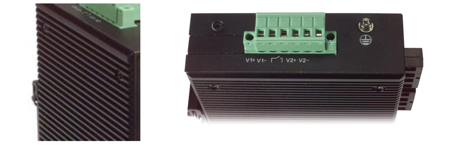
The image on the left details the case of an Industrial Ethernet Switch that acts as the heat sink for the unit. The image on the right shows dual power inputs as well as a dry contact for connecting alarm devices for visual or audio warning in the event of a power supply failure.
Key Design Considerations for Industrial Ethernet Networks
Industrial Ethernet is well understood conceptually, but successful deployments depend on physical-layer and network design decisions that aren’t required in typical office or data center networks. This white paper examines how cabling, connectors, infrastructure and topology choices affect reliability, uptime and long-term performance in industrial networks. It’s a practical resource for engineers who need to design, deploy or maintain systems where Industrial Ethernet is expected to perform consistently under real operational demands.
Recommendations
- opt for Cat6a or fiber in high-EMI or long-distance environments.
- Use M12 connectors for vibration-prone applications.
- Implement PoE where convenient power delivery is required.
- Ensure compliance with IEEE and industrial automation standards.
- Consider L-com’s rugged cables and adapters for reliable field performance.
Conclusion
Ethernet has evolved from being an office/business networking technology to wide spread implementation in industrial networks all over the world. By utilizing Ethernet standards such as VLANs, priority queuing, Rapid Spanning Tree and SNMP network management, industrial networks have become more secure, easier to manage and more robust.
Furthermore, Ethernet is an open standard with support from hundreds of device makers which leads to interoperability among different vendor’s products as well as competitive pricing. Utilizing Ethernet also ensures the protection of legacy technology investments by integrating into existing industrial technologies such as Modbus using an Ethernet gateway device to bridge the two networks. With so many benefits and advantages Ethernet for industrial networks is here to stay.
Frequently Asked Questions
A: Industrial Ethernet is built with ruggedized cables, connectors, and enclosures to withstand heat, vibration, EMI, and moisture.
A: Not recommended they lack shielding and durability, leading to potential failures.
A: Copper cabling supports up to 100 m; use fiber for longer distances or EMI-heavy areas.
A: M12 connectors with IP67/IP68 ratings are preferred for vibration and moisture resistance.