Antenna Installation Considerations
Download the Full Whitepaper (PDF)Executive Summary
Key Takeaways:
- Antenna height and clear line-of-sight directly affect link quality.
- Maintain at least 60% Fresnel Zone clearance for stable connections.
- Proper polarization alignment is critical to prevent signal loss.
- Minimize feedline length and use low-loss cables.
- Grounding and lightning protection safeguard against damage.
- Regular maintenance and inspection ensure long-term reliability.
Introduction
When installing a wireless LAN antenna several factors must be considered before installation in order to obtain optimal wireless signal connectivity.
Why Proper Antenna Placement Matters
When dealing with the installation and expansion of indoor wireless networks several factors must be considered. Most manufacturers of wireless access points and routers indicate a typical range that their equipment can provide. Usually these range estimates require line of sight which means you will need a clear unobstructed view of the antenna from the remote point in the link. In most cases there will be obstacles present in an indoor installation that could affect performance.
Signals generally will not penetrate metal or concrete walls. Other factors that will reduce range and affect coverage area include metal studs in walls, concrete fiberboard walls, aluminum siding, foil-backed insulation in the walls or under the siding, pipes and electrical wiring, furniture and sources of interference. Other sources include other wireless equipment, cordless phones, microwave ovens, radio transmitters and other electrical equipment. Due to the increased gain, installing range extender antennas in the presence of interference could actually yield equal or worse range.
In wireless transmissions, reflections (when wireless signals “bounce” off objects) and multipath (when wireless signals travel in multiple paths arriving at the receiver at different times) are as important as signal strength in determining the success of an installation. A signal will also exhibit peaks and nulls in its amplitude and alteration of its polarization (vertical or horizontal) when propagating through walls, ceilings and reflecting off metallic objects.
Wireless radios have special hardware and software to deal with multipath and signal level nulls, but if the antenna is in a poor location, the radio will not be able to communicate. When trying to get the best performance in a location with a lot of barriers or reflections, it is important to be able to move the antenna in all three axes in order to minimize the effects of multipath and optimize the signal strength.
Understanding Signal Propagation Fundamentals
Before deploying any wireless network, a site survey is recommended. The site survey typically entails installing an access point at each location where user groups are located and then monitoring the wireless signal strength by walking varying distances away from the access points using a laptop with site survey software. The result will show you where you may need more access points to provide sufficient coverage or where you may need to move an access point for optimal wireless connectivity.
Antenna Mounting & Orientation Best Practices
The correct installation height of an antenna depends on the factors outlined below.
1) Distance between the sites: The longer the link, the higher the antenna needs to be due to the earth’s curvature. (This relation is not proportional) See table 1.
2) The Fresnel Zone: This is an electromagnetic phenomenon, where light or radio signals get diffracted or bent from solid objects near their path. See table 1 showing the 60% of Fresnel Zone values (accepted clearing on path). Add this to the earth curvature height.
3) Objects in the path: At a frequency of 2.4 GHz, you need a clear line of sight (LOS). Tree tops will reflect or ground the signal. The theory is that the height of the tallest object in the path of the signal should be added to the Fresnel Zone and earth curvature clearance heights. In your case, you should have to check the height of the trees, hills, buildings or any object on the link path and add this to the measurement for the total of the tower height.
The above three conditions make up the Radio Line of Sight. See Table 1.
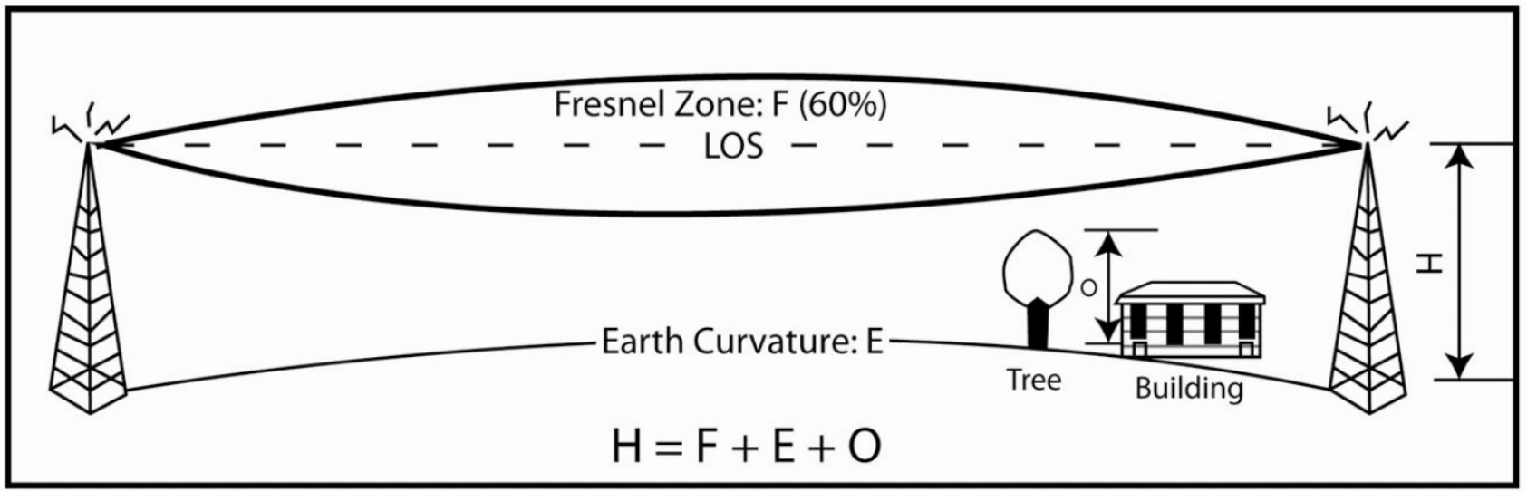
Add these values to find the proper antenna height.
Table 1:
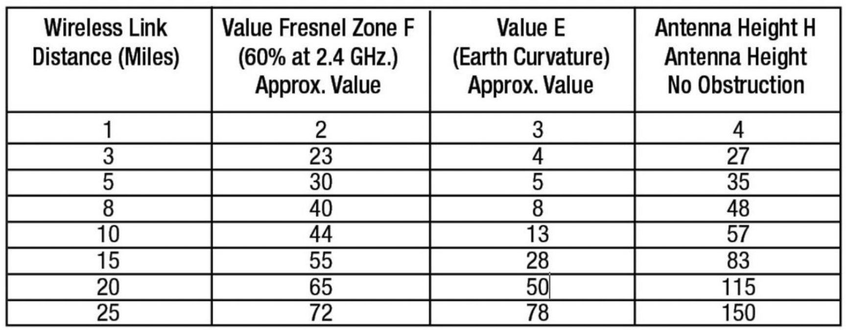
This is theoretical data and there are some cases of customers with working links, with line of sight (LOS) just a few feet over the top of obstacles on their path. We want to emphasize the need for clear line of sight. Trees should not be in the way. We recommend that the height of the tower should be the minimum of the earth curvature plus Fresnel Zone clearance height, making sure that this height is at least 10 feet above the top of any obstructing object before you start testing the link.
Installation Recommendations
- Use a laser alignment tool for precise directional antenna setup.
- Label both ends of each cable for easier maintenance.
- Use drip loops to prevent water from entering connectors.
- Apply dielectric grease on outdoor connectors to prevent corrosion.
- Schedule annual performance checks using signal strength metrics.
A Practical Guide to Antenna Placement and Installation Performance
You can spec the right antenna and still end up with an underperforming link. This resource focuses on the installation variables that quietly determine whether an RF system performs as expected or underdelivers in the field. From Fresnel zone clearance and polarization alignment to feedline loss and grounding, it connects RF theory to the real-world installation decisions that directly affect link reliability and throughput.
Conclusion
To ensure optimal wireless connectivity several rules of installation must be followed. By not considering the factors outlined in this paper you may not receive signal on the receiving antenna end of the link.
Frequently Asked Questions
A: Ideally above nearby obstructions typically 10 to 20 feet higher than surrounding terrain or structures—to ensure a clear line of sight.
A: Signal loss occurs from long cable runs, poor-quality connectors, or obstructions in the Fresnel zone. Using low-loss cables minimizes attenuation.
A: While not always required, grounding provides additional safety and can reduce interference for systems near high-voltage lines.
A: Check every 6 to 12 months, especially after severe weather or when performance drops.
A: Vertical polarization radiates signals up/down relative to the ground, while horizontal radiates side-to-side. Both antennas in a link must match polarization.
