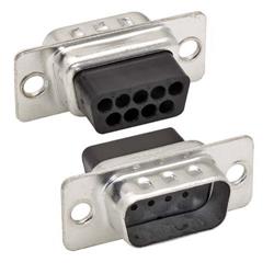
D-Sub
Connection Technology Today
Like the forty-ish professional athlete it is no longer considered fast or sleek, but D-Sub
connection technology is still going strong for one reason – it gets the job done. The D-Sub interface
(figure 1) has survived being replaced by newer, faster, more compact interfaces. USB (figure 2) among others has
replaced D-Sub serial and parallel ports on computers and printers.
Figures 1 (D-Sub interface) and 2 (USB).
DVI, HDMI and
the new DisplayPort interface has started to compete with SVGA (HD15 D-Sub) as the primary video interface on
computer monitors as well. Advantages of D-Sub D-Sub
survival is due to several product features: 1. Engineers prefer the lock down
mating hardware between screw and standoff to the non-secure retention of USB, firewire, HDMI etc. Simply put,
D-Sub hardware can be
permanently locked down and will not come loose due to vibration or jostling (figures 3 and 4). 

Figures 3 (D-Sub cables not mated) and 4 (D-Sub cables mated).
2. Standard D-Sub connectors range from 9 position to 50 position and
high density D-Sub connectors allow for up to 78 positions therefore giving the designer flexibility depending
on how many signals are required in their application. View L-com’s video "The Difference
Between Standard and High Density D-Sub Configurations".
3. Costs for connectors and cable assemblies are reasonably low. 4. Connectors and cable assemblies are available with many options. Printed circuit board (PCB) connectors are
available as through hole or surface mount, can be stacked, and are also available filtered for high electromagnetic
interference/radio frequency interference (EMI/RFI) environments. Cable connectors have multiple options for termination
– solder, crimp/poke, insulation displacement, wire wrap and mass termination. Also available are combination
connectors that reduce the number of signal contacts to accommodate coaxial, high current or high voltage contacts. Disadvantages of D-Sub 1. Although they are called
D-Subminiature, by today’s standards they are anything but miniature. Most designers look to reduce the size of their
products so valuable real estate is taken up quickly with D-Sub connectors. 2.
Because D-Sub connectors are connected to an unlimited variety of cable, there is no defined speed that the user can rely on
without calculating and/or testing individual scenarios. 3. With the exception of some
custom cable assemblies using larger AWG conductors, D-Sub connectors are considered signal connectors, not power.
Therefore they do not readily and economically combine transmission of power and signal as USB and firewire do. Brief History/Tutorial
D-Subminiature connectors were developed in the 1950’s. They are distinguishable by
their D shape which insures correct orientation. When mated, the female connector fits snugly inside the male
connector. Because they are metal a continuous, 360 degree shield can be created throughout the entire cable assembly and
connector system. Contacts are arranged in parallel rows varying from 2 to 4 rows depending on connector size.
There are 5 basic shell sizes, standard contact arrangements range from 9 to 50 positions, high density
range from 15 to 78 positions (figure 5). View
L-com’s "Data Cabling Tutorial" on how and where D-Subminiature products are used.

Figure 5 (Tip on the difference between standard and high-density D-Sub
configurations).
Industry standard commercial contacts are stamped metal while
military rated contacts are screw machined. Contacts are typically gold plated, anywhere from 3 microinch gold
flash to 30 microinch depending on how many mating cycles they are expected to withstand. Current Application Examples
Jim Smith, Production Engineer at HBM Somat, a leading provider of rugged, portable data
acquisition systems states D-Sub connectivity is used throughout their product lines for “reliability and
convenience.” Thirty two signals are required to wire Somat’s thermocouple PCB to a cold junction
compensation box. Somat designed in a standard, off the shelf 37 position D-Sub cable assembly (figure 6) to make the
connections.

Figure 6 (Somat D-Sub 37 position cable assembly).
For more complicated interconnect challenges Somat designed a few daisy chain assemblies
containing several smaller cables all wired into larger DB37 or HD62 connectors (figure 7).

Figure 7 (Somat D-Sub engineering drawing).
These cables make assembly easy, allow for multiple interfaces to be used and take advantage
of D-Sub’s high contact count and secure connection between cable assembly and PCB. Another benefit by
utilizing D-Sub connectors in these cables is the ability to mold the backshell, resulting in a very durable product.
Initially Somat had these cables manufactured with assembled/mechanical backshells. Because these assembled
backshells can’t provide adequate strain relief due to the non-uniform shape of the cable bundle, individual cables
occasionally pulled out of the backshell strain relief (figure 8).

Figure 8 (Example of bad cable where assembled backshell can’t provide strain
relief).
L-com proposed a molded backshell solution which has eliminated this problem and provided a
more professional appearance (figure 9). 
Figure 9 (L-com’s proposed molded backshell D-Sub solution).
Tom Baker, Electrical Design Engineer at Bally Technologies, a premier manufacturer of casino
games and slot machines also uses D-Sub technology in a variety of applications. According to Baker, Bally uses well
shielded SVGA cable assemblies featuring HD15 connectors to “pass stringent EMI emissions requirements.”
Bally also uses serial RS232 DB9 cables for their touchscreen interactive video games, some of which utilize bulkhead
mounted dual sided adapters to pass cables through enclosures.
Matt Nitka, Lead Engineer for a well known medical product manufacturer, shares
Bally’s use of 9 pin D-Sub serial RS232 cables for their touchscreen monitor displays. Also similar to Bally but with
their serial cables, Nitka states they must pass rigorous UL emissions demands and require 360 degree shielding with
negligible EMI leakage. L-com’s premium series of D-Sub
cable assemblies has satisfied this requirement. Industry standard cables use a foil/mylar shield and carry this shield from
connector to connector via an electrically connected drain wire. These cables may or may not shield the area under the
backshell mold. L-com’s premium line of cables adds a tinned copper braid shield over the foil/mylar shield (figure 10)
and a steel internal shell under the overmold (figure 11). The braid provides additional shielding and the shell connects the cable
braid to the connector therefore insuring 360 degree shielding throughout the assembly. 
Figure 10 (Detail of L-com’s premium D-Sub cable with tinned copper braid
shield).

Figure 11 (Detail of L-com’s premium D-Sub cable with steel internal
shell).
Nitka also cited the use of D-Sub cables as the interface to thermal based
printers that doctors use to analyze graphs of various patient tests. With numerous
applications taking advantage of the attractive features of this connector system, D-Sub connectors appear to be in no danger of extinction.
They are simply too versatile, reliable and offer many options for passing signals from point A to B.
If this D-Sub Connection Technology Today content was helpful, please
consider receiving our e-newsletter packed with product
information, tutorials, tips and videos, helpful links, industry news and more.
|